Following the sample program in A2 E-CAM Example – Flying Shear (1) – Basic Operation, this article includes the further introduction of the parameter configuration. Due to the difference in specifications of each flying shear mechanism, it is not appropriate to apply the sample parameters completely unchanged. This article will elaborate the related parameters and the principle for the proper configuration.
— Thanks to Jack Tsai for providing this English translation.
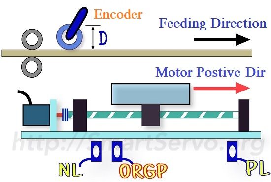
First we define the composition of the flying shear system and the working direction as shown below:
Please make sure the servo drive is Servo OFF, then follow the instructions step by step to modify the parameters.
(1) System Parameters:
- PUU unit and E-Gear Ratio
- The first priority is to define the PUU(Position of User Unit), means it’s defined by the user. In this example, it’s recommended to use micro-meter (µm) as the unit of PUU, which means 1mm=1000PUU, so the E-gear ratio can be obtained based on the mechanical specification. Users can use the E-Gear-Ratio calculation tool to help with the calculation, then set P1-44(nominator) and P1-45(denominator) of the servo drive according to the result.
- Positive/Negative limit switches wiring correctly
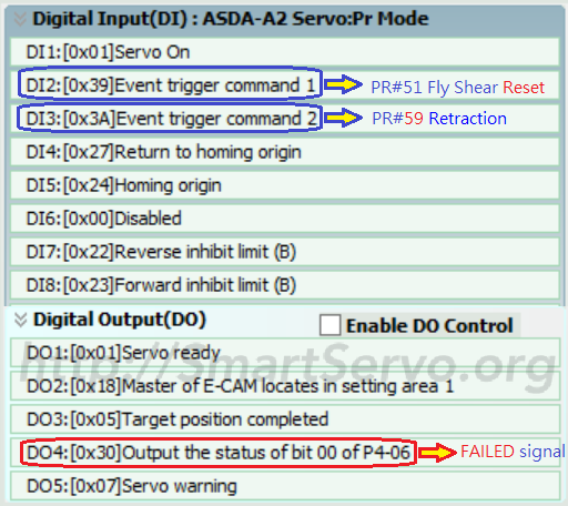
- For safety reason, please make sure the wiring of the positive/negative limit switches correctly before connecting the motor to the mechanism. Please refer to DI configuration figure of the project and configure the parameters correctly:
- DI 7 Negative Linit(NL):P2-16 = 0x22
- DI 8 Postive Limit(PL):P2-17 = 0x23,both are B-contact to prevent malfunction in case of the connection break-down!
- For safety reason, please make sure the wiring of the positive/negative limit switches correctly before connecting the motor to the mechanism. Please refer to DI configuration figure of the project and configure the parameters correctly:
- Master axis pulse source selection
- P5-88.Y=1(from CN 5);2(from CN 1),modify PR#55 as follows:
- from CN 1:modify PR#55,write 0x0001C021 to P5-88.
- from CN 5:modify PR#55,write 0x0001C011 to P5-88.
- P1-00.X:Pulse Type,if from CN1,the correct pulse type needs to be set according to the master axis encoder(0:A/B phase;1:CW/CCW;2:Pulse+Sign).
- Postive pulse-trend:When the encoder is rotating in the feeding direction, the pulse-trend of the master axis received by the servo drive must be positive. P5-18 can be used to monitor CN1 pulses while P5-17 can be used for CN5 pulses. If the value is not correct, interchange 2 signals to fix it。
- P5-88.Y=1(from CN 5);2(from CN 1),modify PR#55 as follows:
- Postive direction of motor rotation P1-01.Z
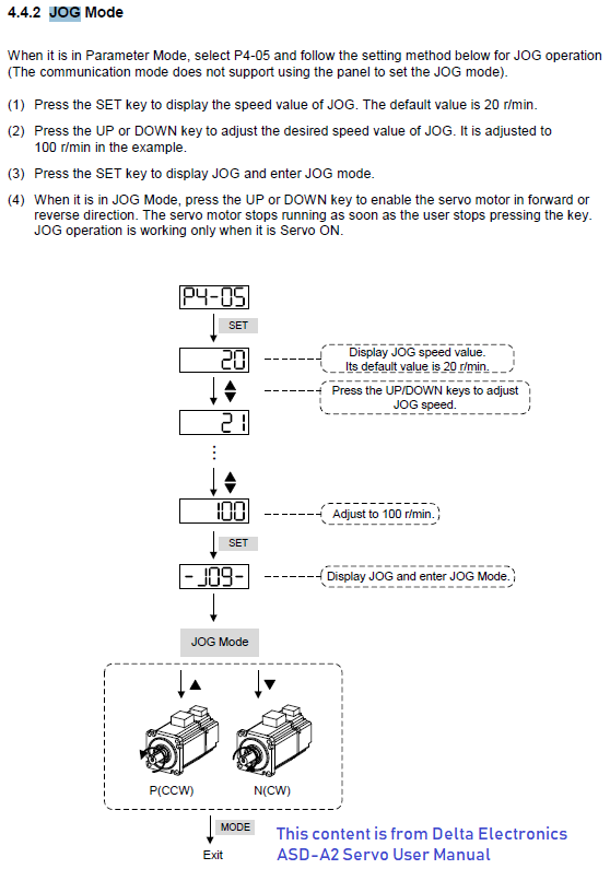
- As shown in the figure above, the positive direction of motor rotation needs to be the same as the feeding direction. The motor speed will be a positive value when it is rotating in the positive direction, which can be verified with the Forward JOG function. If the direction is not correct, modify the value of P1-01.Z (Modification takes effect after reboot)
- Homing method and Home offset(P6-01)
- Please locate the homing sensor ORGP(0x24) close to the Negative limit NL(as the figure shown above), so that it is closer to the starting point of the flying shear. The sample program has set the homing mode as “Homing in Negative Direction”, so there’s no need to change it. After homing is completed, it will automatically move to 0 PUU as the starting point of the flying shear. If the users want to change the starting point, simply adjust P6-01, which is the home offset corresponds to the mechanical reference signal(ORGP).
- Trapezoidal E-CAM curve and synchronous speed matching
- Re-build the ECAM curve, please refer to Creating Trapezoidal E-CAM Table with ASDA-Soft. First set the track length L(unit: PUU) as the total moving distance of the servo motor(the allowable distance without reaching the PL/NL limit switches), then follow the instruction of “matching the Synchronization Speed” step by step to get the proper value of P5-84. At last, download the parameters and the E-CAM table into the servo drive and burn it to prevent data lost when the power is off。
- Define the phase range of the ECAM synchronization area
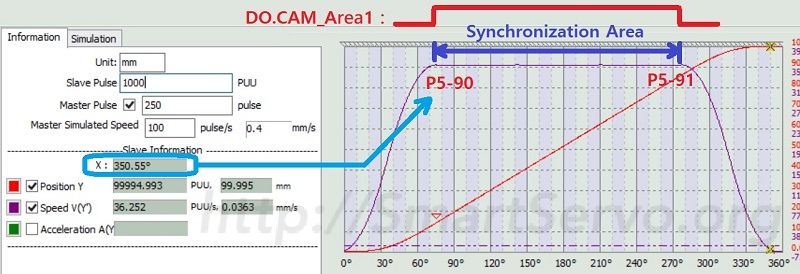
- Set the start and end angle of the synchronization area according to the aforementioned ECAM curve as the output range of DO2:CAM_Area1:
- P5-90:Start angle,DO Off ⇒ ON,as X shown in the figure below indicating the master axis phase.
- P5-91:End angle,DO ON ⇒ Off,refer to DO.CAM_Area setting method.
- Set the start and end angle of the synchronization area according to the aforementioned ECAM curve as the output range of DO2:CAM_Area1:
(2) Production Parameters:
- Cutting length
- Please note: the cutting length (P)[* 1] is described in the pulse unit of the master axis encoder, not the slave PUU. The setting method is:
- if P <=P5-84,set P5-89=P,P5-92=0
- else P > P5-84, set P5-89=P5-84 and P5-92 = P – P5-84
- Please note: the cutting length (P)[* 1] is described in the pulse unit of the master axis encoder, not the slave PUU. The setting method is:
- The retraction speed of the flying shear mechanism
When the above parameters are all set, you can save them first, and power on the servo drive again, then you can start the operation by reference to the procedure in A2 E-CAM Example – Flying Shear (1) – Basic Operation!You can also write a PLC program to control servo’s DI/DOs to achieve the flying shear application.
[* 1]The formula below can be used to convert the cutting length CL(unit: mm) to P(pulses of the master axis):
P = CL × R /(π × D) ,where:
D:Encoder circumference diameter (mm), as shown above
R:Encoder resolution(pulse/rev)