In this article, the formula for the electronic gear ratio of the servo drive for the screw mechanism is derived. The principle of deciding the gear ratio is to first determine the position unit PUU (Pos of User Unit), must be easily observed, usually PUU = 1 or 10 μm, and then calculate the corresponding Gear ratio. Instead of deciding on the gear ratio and then calculating the length of a PUU, otherwise it is asking for trouble (refer to the PUU concept). First, the symbol is defined as follows :
- PUU corresponding to 1 mm (P): How many PUUs respect to 1 mm
- Mechanical reduction ratio (N1 : N2): N1 <= N2 for Deceleration
- Turns of screw rotates (REV): uppercase
- Turns of motor rotates(rev): lowercase, rev = REV ×(N2/N1)
- Pitch of the screw(Pitch): the mechanical movement corresponds to 1 turn of the screw(mm/REV)
- Encoder resolution (R): PLS number per turn of encoder(PLS/rev )
- Electronic Gear Ratio (Num/Den): Scaling factor from PUU to PLS

Electronic Gear Ratio Formula Derivation:
According to the definition of the gear ratio, (PUU) is multiplied by the electronic gear ratio (Num/Den) to obtain the encoder pulse unit (PLS), ie :

If the screw rotates (REV) turns, the motor rotates 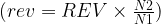
Screw rotates 1 turn :

motor rotates (N2/N1) turn :

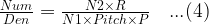
Bring equations (2)(3) into equation (1) and get :
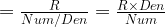
Then get =>
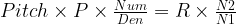
(4) is the Electronics Gear ratio’s formula ! Then, the simulation information is derived. First, the mechanical linear velocity is assumed to be V (mm/sec). Based on this, the current motor speed, the command pulse frequency issued by the controller, and the number of PUUs in one revolution of the motor are calculated as follows :


Calculating the electronic gear ratio is not difficult, but it must also be checked that the motor speed must not exceed its specifications at the required mechanical linear speed. The pulse frequency of the controller must also be fast enough [Note 1], otherwise this set of parameters cannot Use, must be redesigned such as changing the reduction ratio, screw pitch or redo motor and controller selection. This process may be repeated several times. Using this site’s screw mechanism gear ratio calculator can help you save a lot of time ! In addition, the number of PUUs per revolution of the motor should not be too low (it is recommended that it is greater than 5000), Otherwise, the motor is prone to vibration when it is rotating, not smooth enough, and the lower the speed, the more obvious !
[Note 1] This is a limitation of the controller using physical pulses. For example, the pulse output frequency of a PLC may be as fast as 500 KHz. Check whether it is satisfied ! If you use communication control or smart servo with built-in path planning capability, there is no such problem !