This article provides the Arduino source code and usage instructions for the Magnus effect vertical axis wind turbine experimental device. Combined with the previously disclosed circuit diagram, mechanical parts list, and 3D printing STL file, this interesting experiment can be easily implemented. Anyone who is interested can download it and enjoy it ! The dynamic demonstration of this experimental device is shown in the following video:
Arduino source code of this project => iCloud
Other resources for this project => circuit diagram, mechanical parts,STL file
Listed below are the command codes that can communicate through the Arduino serial port to control the behavior of this program. Case insensitive,(*) is default value.
| Code | Fuction | Format/Description |
| M |
Message On/Off |
M0:Message off M1:Message on (*) |
| T |
Test mode |
T0:Normal operation (*), Outputs a sinusoidal command to each motor based on the phase angle. T1:<reserved> T2:Test mode 2,All motors rotate clockwise at the same speed.
The speed command of motors is controlled by Variable resistor(VR) and H command. |
| D |
Phase offset (in degree) |
Dnnn:-360 <= nnn <= 360 nnn represents the phase offset in degree.Added to all motor commands to align with wind direction. When the windward side rotor rotates clockwise and the leeward side rotor rotates counterclockwise, the wind turbine rotates clockwise. ex: D90:add 90 degree to command D180:add 180 degree D-55:subtract 55 degree D0:no offset (*) |
| E |
Enable control |
En:Motor individually enabled,Each bit of n corresponds to a motor… ex: E0:All motors disabled E1:Only motor #1 is enabled E2:Only motor #2 is enabled E4:Only motor #3 is enabled E7:All motors are enabled (*) E3:motor #1 and #2 are enabled |
| H |
High value of motor command |
Hnnn:0 <= nnn <= 100 nnn represents the amplitude value of the motor’s sinusoidal command. ex: H0:all motor stop H50:50% motor command H100:100% motor command (*) |
| L |
Low value of motor command |
Lnnn:0 <= nnn <= 100 nnn represents the scale of the minimum value of the motor sinusoidal command to the maximum value. ex: L0:minimun value of the sinusoidal command is 0,normal sine wave. L30:0 command maps to 30% of the sine amplitude (*) The purpose is to make the motor change direction faster and reduce pauses. |
| C |
Position feedback direction
|
CW:clockwise (*) CCW:Counterclockwise Since this encoder cannot detect the rotation direction, this command is used to specify its direction. The value is (+) for clockwise and (-) for counterclockwise. When this command is changed, it does not mean that the wind turbine will reverse immediately, unless the D command is used to shift the phase by 180 degrees at the same time. Do not change to CCW before you are familiar with this system. |
Step-by-step instructions for using this project code :
- Compile and download the source code to the Arduino UNO control board.
- Open the Arduino serial monitoring window, set the Baud Rate to 9600, and you should be able to observe that the data is continuously listed. The top of the window is the command code input area.
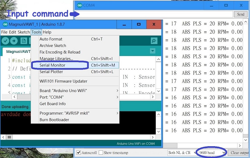
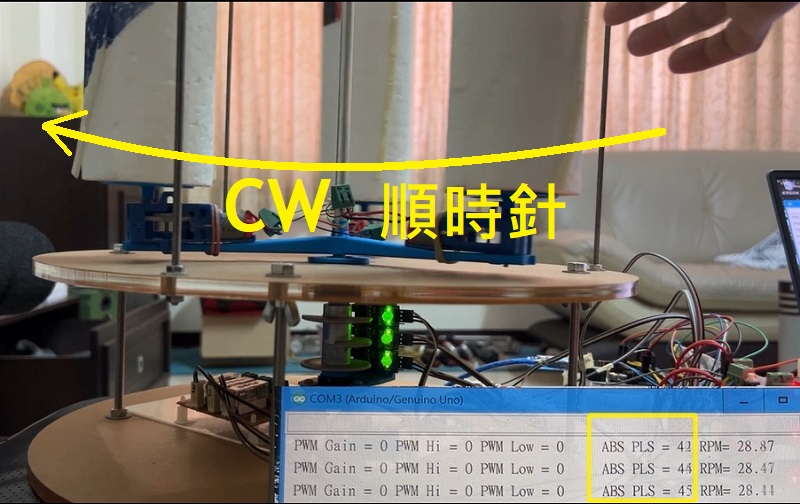
- Manually make the wind turbine rotate clockwise, and observe that the value of ABS PLS continues to increase from 0,1,2…20,21…and returns to 0 after exceeding 79, repeating the process. If it is incorrect, please check whether the photoelectric sensor wiring and sequence (upper/middle/lower) are wrong.
- Turn the VR variable resistor to start the motor, but not too fast.
- Enter the command code “T2” to switch to test mode #2. At this time, all three motors should rotate clockwise.
- If any motor does not rotate, please check the wiring or increase VR. If any motor rotates counterclockwise, reverse the wiring of the motor.
- Enter command code “E1” to confirm that only motor #1 is rotating.
- Enter command code “E2” to confirm that only motor #2 is rotating.
- Enter command code “E4” to confirm that only motor #3 is rotating.
- Confirm that the motors are arranged in the order shown in the figure below, that is, motor 1->2->3 is arranged counterclockwise. If it is incorrect, swap any two motors.
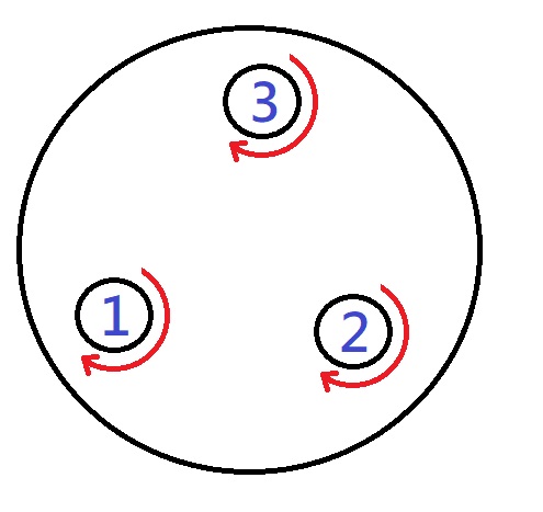
Magnus effect VAWT motor allocation - If the above steps are correct, it means that all wiring and arrangement order are correct.
- Then enter the command code “T0” to switch back to normal mode.
- Manually turn the wind turbine clockwise and observe whether each motor rotates clockwise on the windward side and counterclockwise on the leeward side.
- If there is a deviation in the angle, use the D command to correct it until the status of step 13 is met.
- After the correction is completed, the fan can be turned on and the wind turbine will continue to rotate clockwise.
Operation precautions
- The fan blowing must evenly cover the wind turbine and do not blow only on one side. The wind should not be too strong or too weak, and the distance should not be too far.
- After the wind turbine starts to rotate, the phase lags behind due to the inertia of the rotor, resulting in a deviation in the phase angle and wind direction. This can be dynamically corrected with the D command so that the rotation speed can be increased.
Ref. Magnus effect and Vertical axis wind turbine
Ref. Darrieus wind turbine 3D printing files released