In PLC applications, sometimes it is necessary to communicate with the servo. The easiest way is to use the modbus protocol through RS-232/485. This is a very cost-effective way for small systems with few axes. However, it is often a pity that the application is limited due to the lack of rapid response. For this kind of application, this article takes Delta A2 servo as an example, and provides some acceleration methods to increase the refresh rate of communication and make the command response more quickly. Interested readers can refer to it.
Increase Baud rate : P3-01.X
Increasing the baud rate can reduce the transmission time of each bit. Generally, the baud rate needs to be reduced as the communication distance increases, otherwise the error rate will increase. Therefore, the wiring must be as short as possible and be isolated to resist interference. The packet transmission time can be calculated based on the baud rate. For example, baud rate = 115200, which means that each bit requires 1/115200 seconds. If a byte is in the 8E1 format (see P3-02), it needs 11 bits (1 start + 8 data + 1 parity check + 1 stop), and a 30 bytes packet will cost :
1/115200 x 11 x 30 = 2.8 msec。
Use RTU instead of ASCII : P3-02
If the same content is transmitted in RTU mode, the number of bits in the packet is about half that of ASCII mode, and the transmission time is also reduced by half.
The Modbus commands supported by A2 servo are :
- CMD 06h:Write a 16-bit parameter per packet,An alarm will be generated if the attribute of the written parameter is 32 bit!
- CMD 10h:Write N parameter per packet,N=1~4,16 bit or 32 bit parameters are allowed. Each parameter occupies 2 word addresses regardless of whether the parameter is 16 or 32 bit.
- CMD 03h:Read N parameter per packet,N=1~5,16 bit or 32 bit parameters are allowed. Each parameter occupies 2 word addresses regardless of whether the parameter is 16 or 32 bit.
Use mapping parameters to reduce the number of modbus packets
Because the communication object addresses are usually not continuous, for example, to control DI, you need to write to P4-07, and to trigger PR, you need to write to P5-07. If you write separately, you need to communicate twice, which will be inefficient. Delta A2 servo provides 8 mapping parameters P0-25~P0-32,Taking the above as an example, you can map P4-07 to P0-25, and P5-07 to P0-26. Using CMD 10h to communicate with P0-25~P0-26 at the same time, only one packet is needed, which can greatly improve efficiency. And because each mapping parameter is 32 bits wide, and the above P4-07 and P5-07 are both 16 bits wide, they can be mapped to the high 16 bits and low 16 bits of P0-25 respectively without occupying 2 mapping parameters. Therefore, the benefits of using mapping parameters not only make the address continuous and reduce the number of packets, but also make the communication data compact to improve bandwidth utilization. This is a very important technique. The mapping method can refer to the description of parameters P0-35~P0-42.
Configuration skills of mapping parameters
If you feel that the 8 mapping parameters are not enough, you can configure the parameters required for both reading and writing in the middle section to save space. For example: a total of 9 parameters need to be communicated, (more than 8), if 5 parameters need to be read, 4 parameters should be written, As some parameters may be required for both reading and writing, such as DI: P4-07 and PR: P5-07, When mapping, you can configure the 3 parameters that only need to be read in the mapping area 1~3, and then configure the parameters needed for reading and writing in 4~5, and then configure the parameters that only need to be written in 6~7. When reading, use CMD 03h to read 1~5 at the same time, and use CMD 10h to write 4~7 at the same time, which can meet the demand. If it is still not enough, you can configure the parameters that require frequent communication in the mapping area, and the parameters that are read and written occasionally are not mapped and communicated directly by their address. The concept is similar to PDO and SDO in the CANopen protocol. PDO is suitable for parameters that need to be refreshed frequently, with high efficiency but fixed objects (using mapping); SDO is suitable for random communication parameters, with variable objects but low efficiency.
Communication is synchronized with PLC scan
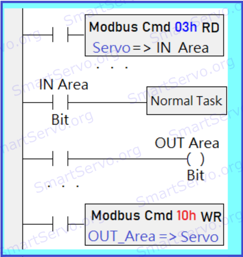
With the above mapping techniques and multi-parameter read/write modbus commands, the program reads/writes the servo’s mapping parameters in one place, so that the required data can be refreshed to the PLC’s memory at one time, It is also equivalent to mapping the servo parameters to the memory of the PLC, much like a memory link. Among them, the reading and writing of the mapping area correspond to different memories of the PLC, such as IN_Area and OUT_Area in the figure below. And the data refresh is synchronized with the PLC scan cycle, so that the content of the communication can remain unchanged during a scan cycle to avoid programming logic errors.。
The PR mode of Delta A2 servo has origin search, point-to-point motion, and also includes electronic cams, If the communication efficiency of modbus can be improved, the PLC can effectively use these functions, which is sufficient for general applications, and it is not necessary to use CAN bus or EtherCAT. In this way, in addition to simplifying the system, it can also save costs, which is especially competitive for small systems.
Ref. Delta A2 Servo Quick Start and FAQ,Parameter List of Delta A2 Servo。