This article contains frequently asked questions and alarms for the Delta ASD-A2 servo system for readers’ reference:
Q1,AL.13/AL.14/AL.15 is displayed on power-up, how to deal with it?
A => For safety reasons, the default functions of the servo DI 6/7/8 are reverse limit/forward limit/emergency stop, and are all B (normally closed) contacts, so when there is no limit switch connected, The above alarm will occur when power is applied. If the motor (not the linear motor) is not connected to the mechanism, the user only wants to test it. You can temporarily remove these protection functions by setting the hundred digits of P2-15, P2-16, and P2-17 from 0 to 1. , change to A (normally open) contact; or directly set all three parameters to 0, which means to turn off these protection functions ! Users should take extra care when testing and fix the motor firmly for safety !
Q2,How to set servo’s operation mode?
A => The operating modes of Delta A2 servo mainly include: position mode/speed mode/torque mode, and also includes the combination mode of three. The parameter P1-01 can be used as a selection. After the setting is completed, it must be powered on again to take effect.!
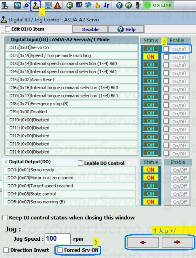
Q3,How to force the servo “Servo ON”?
A => When testing, it is often necessary to force Servo ON. The methods are :
- Set parameter P2-30 = 1 to Servo ON, then set = 0 to turn off !(P2-30 not stored when power is off)
- If DI.SON that controls servo ON is not connected, it can be changed from A contact to B contact. By default, DI 1 is preset to SON. Just change the corresponding parameter P2-10 to 0x0001 to force the servo ON ! Note that this modification will be stored after power off. Remember to change back to 0x0101 to return to A contact after the test is completed..
- Use the DIO Control Panel in ASDA-Soft Software => Item 2 or 3 can force Servo ON.
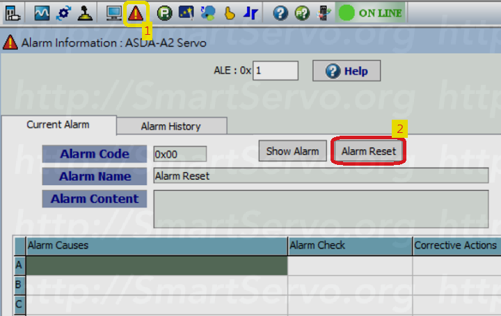
Q4,How to reset the servo alarm?
A => Servo alarm (AL.XXX) can be reset by the following methods:
- Press the up and down keys on the drive’s front panel simultaneously for 2 seconds ! (P1-01 = except B or C communication mode)
- Write 0 to parameter P0-01 to clear the alarm, read to display the current alarm number.
- Turn on DI.ARST (0x02) to clear the alarm
- Use the ASDA-Soft software’s => Alarm reset function
- Some alarms cannot be reset by the above method (such as AL.011), only power off and then power on again !
- Refer to this site’s => Trouble shooting summary Page
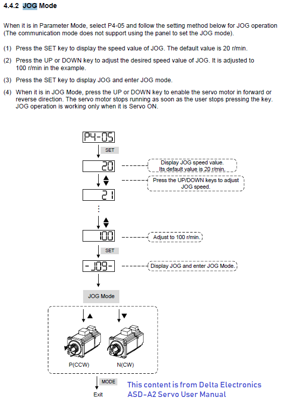
Q5,How to perform test run (JOG)?
A => There are two ways to do this:
- Use the drive panel: you must first Servo ON, then set the jog speed parameter P4-05, then use the UP or DOWN keys to execute jog, refer to => Delta servo JOG process!
- Use the DIO & JOG Control in ASDA-Soft Software => Item 3 or 4
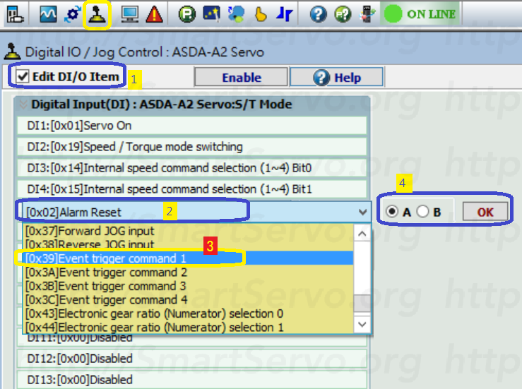
Q6,How to configure DI/DO functions?
A => DI 1~8 corresponds to parameters P2-10 ~ P2-17; DO 1~5 corresponds to parameters P2-18 ~ P2-22, which can be directly set by the ASDA-Soft parameter editor or digital IO control panel => Step 1 ~4 to set.
Q7,How to communicate with A2 servo via MODBUS?
A => The communication port of Modbus is located at CN3. For the wiring method, please refer to Section 3.6 of Delta A2 Servo User Manual. The parameter settings are as follows :
- Node number: P3-00, can be set 01~7F, it needs to be powered on again to take effect !
- Baud rate: P3-01, preset is 38400
- frame format: P3-02, set data bit / stop bit / parity check, and ASCII or RTU.
- Physical layer: P3-05, set to 0 using RS-232 and set to 1 for RS-485
- Parameter Address: Chapter 8 of the manual lists the communication addresses for each parameter. Each parameter occupies 2 words (32 bits).
For more information => How to improve Modbus communication speed.
Q8,Which parameters are non-volatile (still remembered after power off)?
A => The attributes of the parameters are marked with the following symbols, as long as none of the labels (■) and (★) are non-volatile :
(★)Read-Only,Can only read values, for example: P0-00, P0-09, etc.
(▲)Writing is prohibited when Servo On, for example: P1-00, P1-46, etc.
(●)Re-powered to take effect, for example: P1-01 and P3-00
(■)Volatile, restore default values when power is turned back on, for example: P2-75 and P5-88
Q9,How to avoid writing parameters too frequently to damage EEPROM?
A => In general, the parameters that need to be written frequently in the A2 servo are designed to be volatile (■). If you can’t avoid frequently writing non-volatile parameters during use, be sure to set P2-30 = 5 to avoid too much writing caused EEPROM damage!Note: P2-30 itself is volatile, so it must be rewritten every time it is powered up!
The above summarizes the common problems of A2 servo entry for readers’ reference. If there is any unsatisfactory, please leave a message below to make the content more fulfilling, thank you !