<= See All alarms of Delta servo
| Name | Description | ALM | WRN | SRV ON | Clear Way |
|---|---|---|---|---|---|
|
AL.170 Heartbeat or |
Heartbeat or NodeGuarding error |
⊗ | Yes |
NMT:Reset node/ 0x6040.Fault Reset |
<= See All alarms of Delta servo
| Name | Description | ALM | WRN | SRV ON | Clear Way |
|---|---|---|---|---|---|
|
AL.170 Heartbeat or |
Heartbeat or NodeGuarding error |
⊗ | Yes |
NMT:Reset node/ 0x6040.Fault Reset |

In this article, the formula for the electronic gear ratio of the servo drive for the screw mechanism is derived. The principle of deciding the gear ratio is to first determine the position unit PUU (Pos of User Unit), must be easily observed, usually PUU = 1 or 10 μm, and then calculate the corresponding Gear ratio. Instead of deciding on the gear ratio and then calculating the length of a PUU, otherwise it is asking for trouble (refer to the PUU concept). First, the symbol is defined as follows :

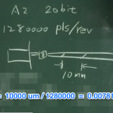
The PLS unit is based on the resolution of the encoder. Take Delta A2 servo as an example. Although the resolution of the encoder is 17 bits/rev or 20 bits/rev, the PLS units are all set to 1280000 PLS/rev, which cannot be changed by the user. That is, when the electronic gear ratio is set to 1:1, the driver must receive 1280000 pulses then the motor will make one revolution.Due to the high resolution, the PLS unit is suitable for inner motor control of servo drives. However, in the motion control system, an absolute coordinate system must be established. If PLS is used as the position unit, neither the command nor the feedback is suitable, the reason is as follows :
<= See All alarms of Delta servo
| Name | Description | ALM | WRN | SRV ON | Clear Way |
|---|---|---|---|---|---|
|
AL.011 Encoder Error |
The encoder produces abnormal pulse | ⊗ | No | re-power on |
<= See All alarms of Delta servo
| Name | Description | ALM | WRN | SRV ON | Clear Way |
|---|---|---|---|---|---|
|
AL.303/3E3 SYNC Time-out |
The synchronized signal, SYNC of CANopen has not been received in time |
3E3 ⊗ |
303 ⊗ |
303:Yes 3E3:No |
NMT: Reset node/ 0x6040.Fault Reset |
<= See All alarms of Delta servo
| Name | Description | ALM | WRN | SRV ON | Clear Way |
|---|---|---|---|---|---|
|
AL.301/3E1 CANopen SYNC fail |
CANopen IP mode fails to synchronize with the controller. |
3E1 ⊗ |
301 ⊗ |
301:Yes 3E1:No |
NMT: Reset node/ 0x6040.Fault Reset |
<= See All alarms of Delta servo
| Name | Description | ALM | WRN | SRV ON | Clear Way |
|---|---|---|---|---|---|
|
AL.009 |
Position error exceeds P2-35 | ⊗ | NO | DI.ARST |

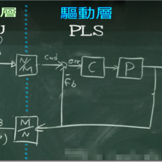
In the motion control system, there are a number of position counters to record the current position, commands and errors of the machine. It is not appropriate to use PLS as a unit (for reasons see Link). Therefore, a new position unit must be introduced, called the Position of User Unit (PUU), which is similar to the Pulse Equivalent Unit in the traditional system that uses pulses as the position command , indicates the moving distance of a pulse. Because the current control system can send commands through communication, there is no physical pulse, the user can be more freely choose the desired position unit, ie PUU. The relationship between PUU and PLS is the electronic gear ratio (N/M) defined as follows:
PUU (counts) * N/M (electronic gear ratio numerator/denominator) = PLS (counts)
<= See All alarms of Delta servo
| Name | Description | ALM | WRN | SRV ON | Clear Way |
|---|---|---|---|---|---|
|
AL.017 Abnormal EEPROM |
It is in error when DSP accesses EEPROM | ⊗ | No | If the alarm occurs,then parameter reset is a must. And re-servo on again. If it happens during the operation, please turn DI.ARST on to clear the alarm. |